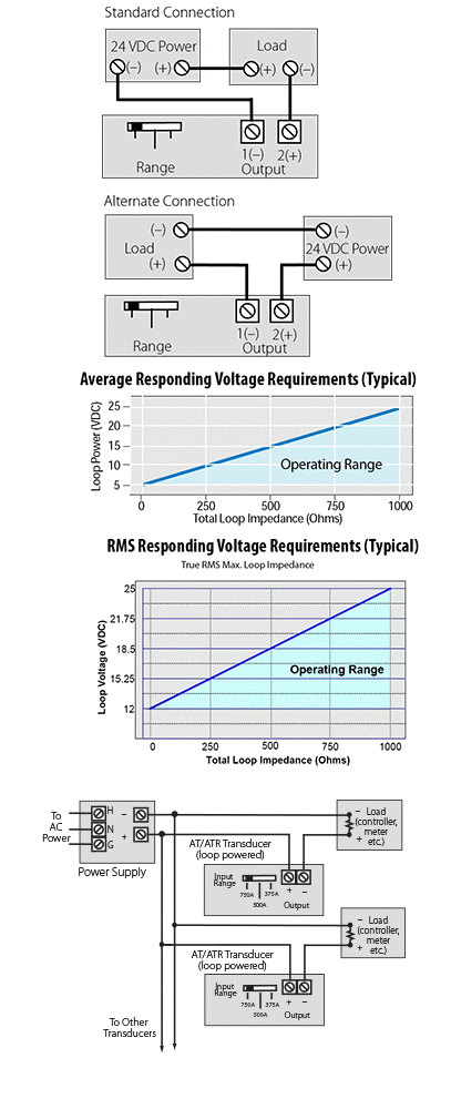
Please note that all loop powered transducers are polarity sensitive, but if the connections are reversed, the transducer is protected from damage internally. This does not mean that the load connected to the transducer is protected, so care must be taken.
NK Technologies provides these connection diagrams for general use. Some manufacturers of programmable logic controllers and panel meters include the 24 VDC power supply to drive the 4–20mA signal internally. Please be sure that the PLC input module requires an external power supply before adding one to the loop circuit.
Voltage Requirements
While the model number indicates that the power supply voltage must be 24 VDC (24L), there are minimum and maximums for each sensor design. Most of the average responding models need an absolute minimum voltage of 5 VDC at the sensor terminals, while the RMS responding models require at least 12 volts to operate. Most sensors have a maximum allowed in the output circuit of 40 volts. There will be voltage drop caused by the resistance in the output wires and any connections made in the circuit. Always check the voltage at the sensor terminals while troubleshooting.
Multiple Sensors - One Power Supply
Connecting several loop-powered sensors to one power supply is easy. Just connect them in parallel as shown in the drawing to the right. To size the power supply, calculate that each sensor draws less than 2 VA. If you need to connect ten sensors to one supply, the supply should have a capacity of at least 20 VA. Using a power supply with larger capacity will not cause a problem.
Why use a loop powered sensor? There are many reasons; the first is that a current output is much less susceptible to external electrical noise than voltage output designs. While it is good practice to always use a twisted, shielded pair to transmit sensor outputs to the controller or meter, it is essential when the output is a low voltage signal. The twisting tends to cancel electromagnetic interference induced from other cabling. This is common in data communication cable like Ethernet, where the data is transmitted only in on or off values. Adding shielding may improve the analog signal stability by reducing the effect of interference from solid-state switching devices, relay contact arcing or other power line disturbances. Running shielded cable for very long distances is costly. Using a current output sensor provides a steady output while the voltage in the loop circuit drops from the resistance of the wire. In this way, industry standard 4–20mA signal can be carried thousands of feet and still produce an accurate output at the receiving end.
The simplicity and reduced cost of using just two wires for both signal and power is another plus. Sensors that are self-powered (actually deriving power from the measured property) will inherently produce a zero signal when the measured parameter is zero, but providing power from an external source allows the output to produce a “live zero,” generally 4mA. This output when there is zero of the measured value confirms that the power supply is energized and that the sensor signal cable is connected properly. Due to the low voltage and low current values, most electrical codes allow the sensor power and signal wiring to be installed without using conduit, which provides a cost savings.


