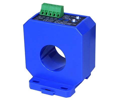
DS1-FD Series DC Current Switch
DS1-FD Current Relays monitor AC or DC loads: motor, crane, or welding equipment. The relay features a large aperture and solid-core design that allows for quick installation, just thread the conductor through the sensing window (aperture) and reconnect on the other side. The DC current operated switch output is isolated from the monitored circuit and can switch up to two amps up to 125 VAC, or two amps to 30 VDC. The output contacts can reset to original condition on current fall or latch in the tripped condition. The trip point (where the output relay changes state) can be adjusted between 20 and 400 amps by adjusting two potentiometers. One provides a “coarse” adjustment; the second allows for fine tuning of the trip point. The sensor mounts on a back panel or a DIN rail, and is designed to accommodate wire sizes for loads up to 400 amps or higher. The maximum current is unlimited, so current higher than the highest adjustment point will keep the relay in the tripped condition.
FACTORY CALIBRATED AND WARRANTIED FOR FIVE YEARS
- Trip point to 400 ADC or 338 AAC.
- Sensor is not polarity sensitive with regard to the monitored circuit.
- Designed for longest life and reliability.
SINGLE POLE, DOUBLE THROW RELAY OUTPUT
- Can control an AC or DC circuit.
- Compatible with most automation and control systems.
- Both NO contact for alarm (closing on current rise) and NC contact (opening on current rise) for disconnecting applications.
- Automatic reset or latching output available.
- Dual potentiometers allow for accurate trip point adjustment.
EXTERNALLY POWERED
- Simple and reliable connection.
SOLID-CORE CASE
- Sensing window provides ample space for single or multiple conductors.
DIN RAIL OR PANEL MOUNT
- Simply snap onto a DIN rail or attach with screws to a panel for secure mounting.


