NK Technologies offers two methods to produce a signal proportional to the current through a current transformer, which can be connected to a programmable logic controller or panel display without any other equipment required. The single pass method passes the wire through the apreture once; the double pass method passed the wire through the sensor’s aperture twice. Choose the method that works best for your application.
While current transformers appear to be quite simple, a proper installation should be studied before installation. All current transformers have a maximum burden specification that designates how much impedance can be connected to the current transformer secondary safely without causing the accuracy to decrease. This burden is stated as volt-amperes or VA. The burden takes the connected load resistance including the driven load (power monitor, display or signal converter) along with the resistance of the wires carrying the five amp secondary. The farther the current transformer is located from the load, the greater the resistance.
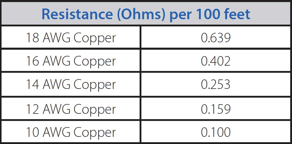
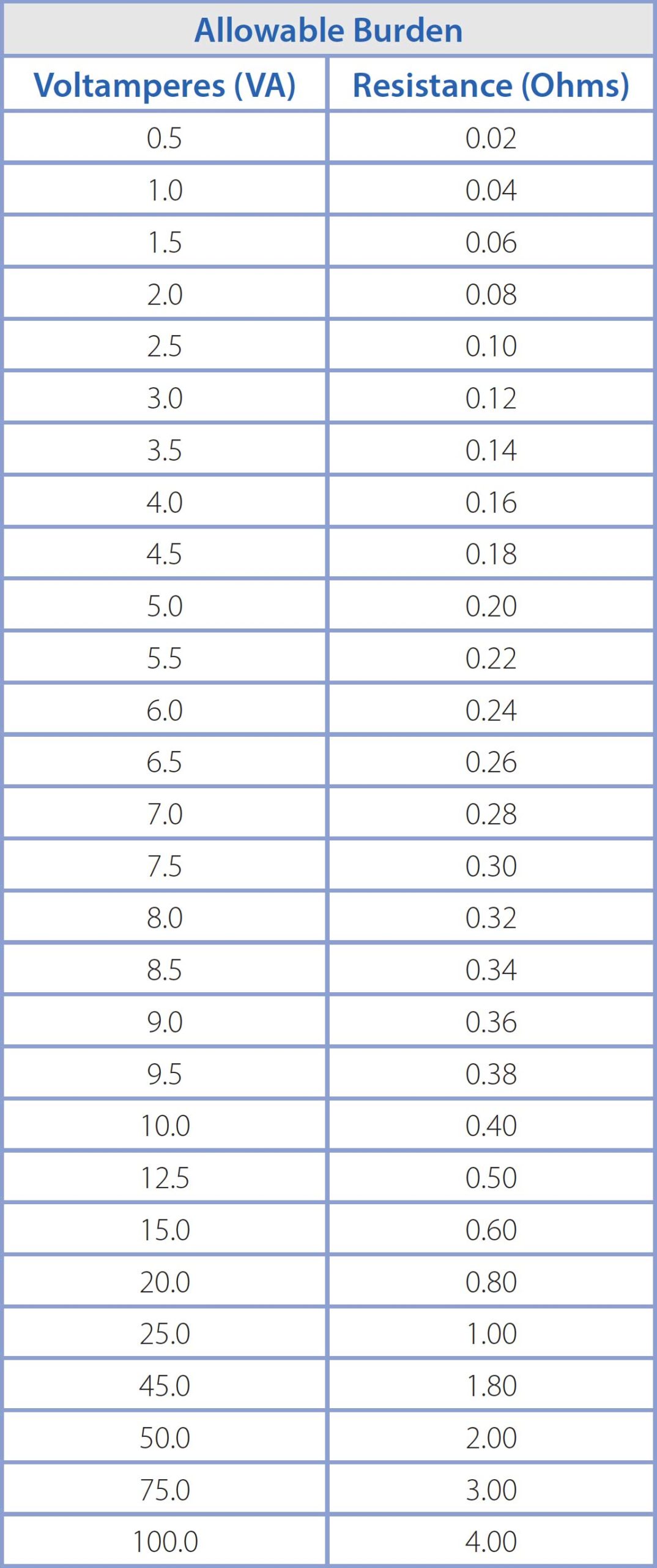
As an example, our CT-0500 - 5-MS is a CT with a ratio of 500:5 and has a specified maximum burden of 5.0 VA; that relates to 0.20 ohms. Using 16 AWG copper wire to carry the current transformer secondary the distance from the CT installation point to the load should be less than 3.8 feet. Larger wire will allow the distance to be increased, but the whole installation needs to be reviewed before action is taken. (See the tables on page 2 for resistance and VA ratings.)
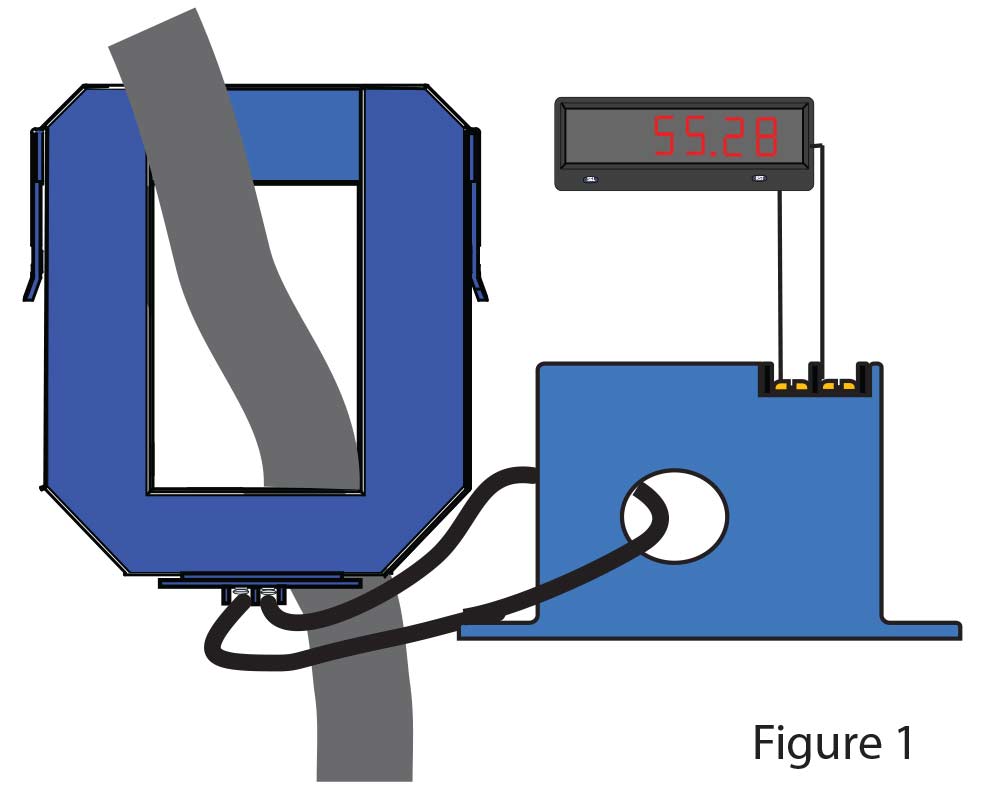
NK Technologies’ AT series current transducers produce 4–20 mA, 0–5 or 0–10 VDC proportional to the AC current through the sensing window. The AT0-420 - 24L-FT has a range of 0–5 amps, so if the 500:5 ratio CT has 500 amps present, the AT sensor will produce 20 mA. (See figure 1.)
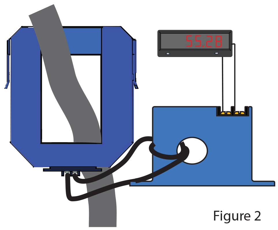
The self-powered, voltage output models have a low range of 0–10 amps (AT1), so if the CT secondary is looped through the sensor twice, the output will be 5 or 10 VDC with 500 amps through the CT. There is no physical contact with the wire, and this approach adds virtually no burden to the current transformer. The sensor can be installed any place over the secondary lead, and any previously connected load can remain in use or the secondary leads can be shorted together. (See figure 2.)
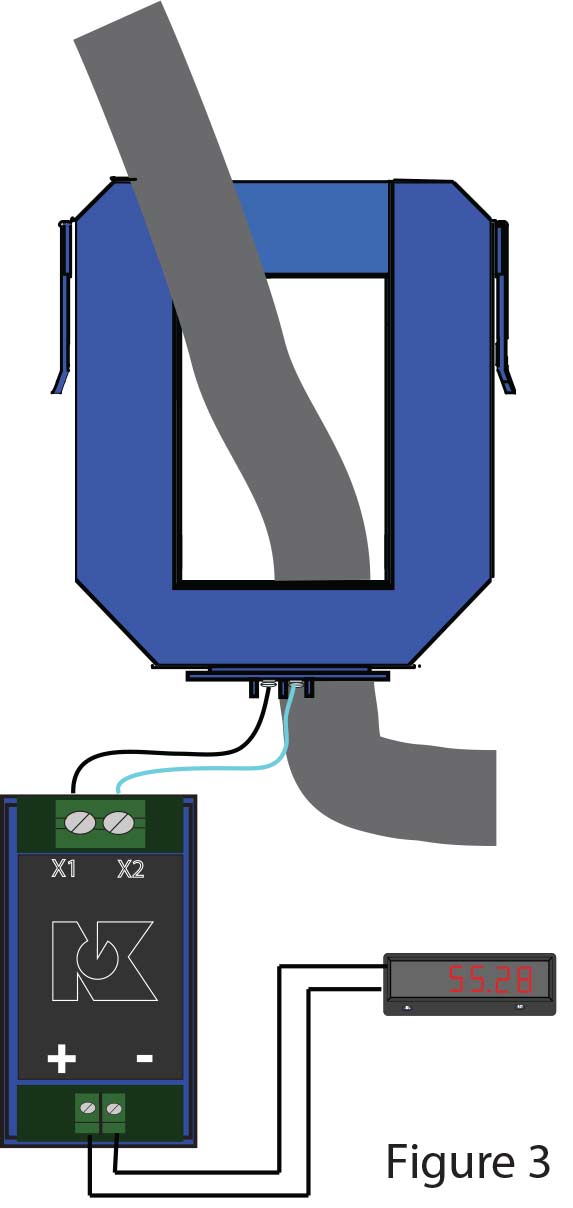
The CTC-05A-420 - 24L-DIN requires the CT secondary leads to be terminated on the converter, and adds 0.668 ohms to the CT burden. The same distance issue applies, so calculating the secondary lead size against the distance from the CT to the converter should be checked. The CTC was not intended to be used with multiple loads on the output terminals. Adding a second set of wires in parallel to operate a display or power monitor may not work out well. Doubling wires under one terminal screw can add more resistance and result in excessive burden, plus the impedance of the load driven with the CT secondary must be included in the total burden calculation. (See figure 3.)
First check the current transformer burden to find the maximum the CT can drive with the stated accuracy. Calculate the resistance of the wires out to the load (panel meter, power monitor, etc.) and back based on the lead length required and the wire size you will use.
Find the impedance of the panel meter, power monitor, or in this example the CTC signal converter and add that to the resistance of the wires.
If a current transformer is being installed 50 feet from the CTC signal converter and 18 gauge wire is used, the impedance burden on the current transformer will be 0.639 ohms in the wires out and back, plus 0.668 ohms in the converter. This means the current transformer VA rating must be around 45.0 VA to get an accurate reading. Larger secondary wires and a shorter distance would allow for a current transformer with a lower VA rating to be used. If the secondary current is carried with 12 AWG, the CT selected could be rated at 25 VA.
Using NK Technologies’ AT or ATR current sensors (for distorted current wave shapes) over the secondary of the current transformer will not have this problem as the current sensing part of the sensor is within inches of the signal converter and both pieces are engineered to work as a pair. The 4–20 mA output can travel a very long distance without causing any issues.

