Current transformers for instrumentation have been in use since the late 1890’s, and accurate non-contact window type  CTs were patented by Westinghouse in the late 1920’s. The first split-core models with suitable output accuracies were introduced in the 1960’s, so while they seem to be an ancient method to measure AC current, refinement took quite some time after the first AC motor patent by Nikola Tesla in 1888. Now measuring the current and power consumption of a motor is more important than ever.
Today there are many methods of measuring electrical current. When the requirement is to replicate the primary current wave shape, as required to measure wattage consumption, toroid based current transformers are the most common and least expensive method available. NK Technologies’ CTs are designing to be used in power metering applications by connecting the secondary to a power monitor.
If the goal is to reduce energy costs, measuring power in watts consumed is an essential tool in understanding where and when power consumption occurs. Measuring wattage requires that the system voltage and current use be compared simultaneously so that the power factor can be calculated. Wattage is calculated by multiplying the voltage by the current in amperes and then by the power factor. The days of spinning wheel watt-hour meters, which utilize the full voltage and current of the monitored circuit, are waning. Solid-state devices have been developed that are more accurate and can provide more information to recording devices like data acquisition systems, computers, and programmable logic controllers. With digital power measurement, the primary voltage is reduced through a potential transformer (either internal or external). The primary current, regardless of the magnitude, but dependant on the CT model, is reduced to a lower magnitude, usually five amps in North America. When the replication of the current wave shape matters, as when monitoring power, the H1 side of the CT must face the source, and the terminal marked X1 will be the phase indicator connected to positive on the watt meter.
A current transformer can also be used as an input to a current relay or transmitter, or to reduce the current so that an NK Technologies’ current switch or transducer can be utilized. Simply short the secondary of the CT through the sensing window of the sensor and a trip point between 1 and 5 amps can be established with a current switch, or a transducer with a range of 0–5 amps can be used, one with a range of 0–10 amps if the CT secondary is looped through the sensor twice.
New CT-LS Series Large Aperture Current Transformers
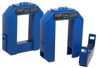
NK Technologies’ CT-LS Series 5A secondary current transformers offer a compact, cost-effective means of measuring primary current. These current transformers feature an extra-large sensing window and a split-core design that provides an easy-to-install method to measure AC current. The CT-LS Series measures current from 0–800 to 0–1600 amps and can be connected to NK Technologies’ CTC Series Signal Converter to convert the CT output to 4–20mA.
Split-Core Housing: Allows the transformer to be installed after the conductors are in place. Pull the top bar off the sensing ring and set the transformer underneath the wires or bars.
Extra-Large Sensing Aperture: The 2.3 inch wide by 3.42 inch high window will easily accommodate the conductors. Multiple wires per phase will pass through the sensing window without extra effort.
