 Producing power using photovoltaic panels has grown exponentially in the past decade. The larger the panel installation the more likely the output direct current voltage will be higher than 600 volts and up to 1500 volts in many places. The primary purpose for the higher voltage is to reduce the conductor size for the same wattage output. Since the current falls as the voltage increases, smaller wire can be used without consequence. Simple in concept, but more difficult to find measuring and control devices rated for the higher potential.
When a certification facility like Underwriters Laboratories tests a current sensing device, they assume that the device might be installed over a bare wire or bus bar, with no insulation. The overall design of the installed control or measurement device must be such that there is no chance of shock or flashover from the conductor to the sensor power supply or output terminals. Sensors for these purposes were originally designed using the same dimensions and housings used for AC circuit measurement, where the voltage seldom exceeds 600, although there are countless motors powered with 2400 and 4160 VAC. These medium voltage AC driven motors are consistently fed with insulated conductors since the final termination in the attached junction box has little area available for space between bus bars.
To accommodate the higher DC voltage used in photovoltaic power generation, different current and voltage sensor designs were needed to measure and monitor these parameters. Voltage measurement requires significant space between the wires and the traces on the circuit board to eliminate the chance that the voltage will arc between the conducting points. Current sensing requires a large air gap between the conductor passing through a ring and the sensor terminals to avoid the same possible condition.
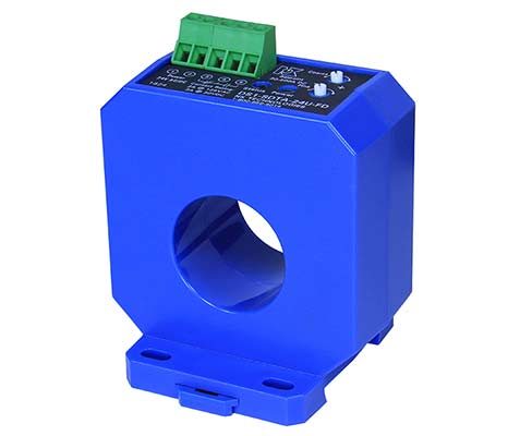
With a sensing window large enough to accommodate a conductor carrying 400 amps and enough spacing between the conductor and the power supply and output signal terminals to pass UL testing for voltages up to 1500 VDC, the new DT- FD series housing solves the problem of safety when measuring current. The sensor can also be mounted in any orientation: vertical, horizontal or any combination of the two.
The sensor output can be configured for output with DC current flowing in one direction (unipolar), or in two directions (bipolar and bidirectional). NK Technologies offers both current and voltage output types to work with most panel meters, programmable logic controllers or data acquisition systems. The outputs can be read by many gateways for conversion to the Industrial Internet of Things so the sensor data can be read easily over connected access devices.
DT-FD Series HV DC Current Transducer
DT-FD series DC Current Transducers provide a large sensing window and the ability to monitor circuits with voltages up to 1500 VDC. The sensor can be mounted on a DIN rail, or be attached to a back panel with screws or suspended on the conductor. Easily accessible power supply and output-signal, finger-safe terminals are located on the top of the sensor to allow for a clean and trouble-free installation. The one-piece design combines the current sensing elements and the signal conditioning to provide an output compatible with most control systems, increasing the safety and accuracy of the installation.
