Designed & Assembled in the USA
NK Technologies manufactures ground fault relays which can be used in a wide range of applications from operating a shunt trip circuit breaker to providing an alarm contact or analog signal to a programmable logic controller. This application guide focuses on using a ground fault relay with a shunt trip breaker, using a commercial kitchen as the example.
The 2020 & 2023 NEC Article 210.8 (B) through (F) requires GFCI protection in an expanded list of locations, including commercial kitchens. Commercial kitchens with high amperage (30A and higher) appliances can utilize a shunt trip circuit breaker combined with a ground fault relay sensor. Jurisdictions often require or prefer UL Listed products and the AGU and AGL Series are both UL Listed.
To meet the intent of the NEC requirement, the following key elements must be satisfied:
- Class A, trips when fault current within 4 to 6 mA range
- Trips in an “established period-of-time” or faster
- Shall have manual “push to test” feature

The first step is to determine the diameter of the monitored wire bundle. This wire bundle must pass through the aperture of the relay. Most common commercial applications will fit in the AGU Series, otherwise the larger aperture size of the AGL Series is recommended. See the “Notes section” below for common scenarios.
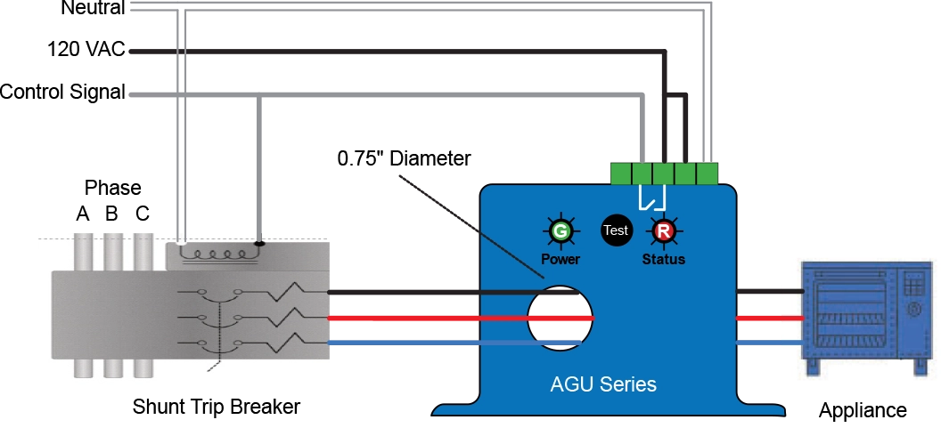
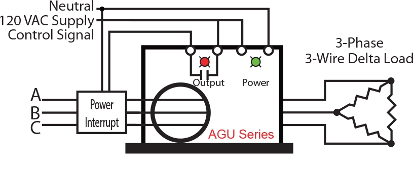
The drawing above shows an NK AGU Series ground fault relay powered by 120 VAC. The same 120 VAC source is used to energize the shunt trip circuit once the control signal is activated by the AGU Series relay. The monitored branch circuit is 3-phase, 240 VAC in a 3-wire delta configuration. All three wires (no neutral & never ground) pass through the aperture.
If a ground fault >5 mA occurs at the appliance, the AGU sensor detects the fault, and closes the control signal relay. This in turn applies 120 VAC to the shunt trip solenoid, causing it to trip the circuit breaker and de-energize the branch circuit and appliance.
The green LED will light when power is applied to the sensor and a red LED indicates that the sensor has tripped.
Notes for Bundled Wire Size:
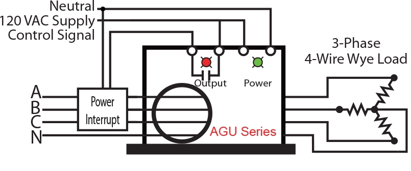
All current carrying conductors must pass through the sensor aperture, including the neutral if the load uses one. Do NOT pass the ground wire through the aperture.
Monitored circuits can be up to 600 VAC and meet the specifications of UL. Circuit amperage determines the wire gauge required to meet code… and those wires (the wire bundle) must physically fit through the aperture of the relay.
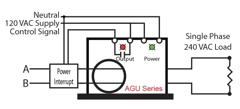
For 240 VAC single phase solutions, the monitored circuit will contain the phase A and phase B wires. Both wires must pass through the aperture of the relay.
Ground Fault Relay Models Discussed
with 5 mA trip point (0.75” Aperture)
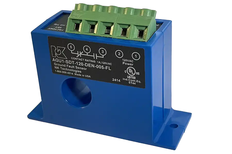
Model# AGU1-SDT-120-DEN-005-FL
with 5 mA trip point (1.76” Aperture)
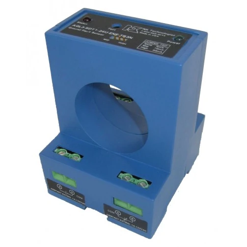
Model# AGL1-SDT1-120-DEN-005

