Designed & Assembled in the USA
The VT3 Voltage Transducer Operation
 The VT3 Series of Voltage Transducers are designed to monitor 3-phase circuits with nominal input voltages of 120, 240, and 480 VAC up to a maximum of 600 VAC. Overall voltage quality can then be logged into a PLC and monitored in real time.
RMS voltage measurements are more accurate and reliable, making the VT3 significantly more robust than an “averaging” transducer, especially in noisy environments. With four industry-standard outputs, the RMS voltage of each phase can be monitored. The fourth output provides the average across all three phases.
The VT3 Series can be powered externally by either 24 VAC/VDC (VT3-OS) or 120 VAC (VT3-OL).
A single leg in a 3-phase power supply can experience phase loss due to a tripped breaker or open circuit. Connected motors and equipment can draw large amounts of current on the remaining two phases, resulting in overheating and damage to those devices. When power loss occurs on a single phase, the normally open VT3 Phase Loss Detection relay activates and can be used to trigger an alarm circuit.
All NK Transducers are UL Listed, which is not always the case with competitive products.
Product Selection
To select the appropriate model number, start by identifying the necessary configuration. Sometimes, the decision is
straightforward based on existing application requirements. In other situations, there is flexibility in choosing the best option for your specific application.

Step 1: Input Voltage Range
VT3 Series is designed for 3-phase applications at 120, 240, and 480 VAC. The input voltage ranges provide a guard band to detect both over-voltage and under-voltage conditions.
For example, choose the 0-150 VAC model to monitor 120 VAC nominal input voltage. Use the 0-300 VAC model to monitor 240 VAC and the 0-600 VAC model for 480 VAC.
Over-voltage conditions up to 25% of the nominal target input voltage can be detected, as shown by the maximum voltage in the table below.

If an under-voltage condition occurs, the phase loss detection relay will close, triggering an “alarm” condition. The relay trigger will occur when the input voltage drops 25% below the nominal target voltage.
Step 2: Output Signal Type
There are three output signal options: 0-5, 0-10 VDC & 4-20 mA. The output is usually fed into a control system (PLC) or data logging system. Choose a VT3 model that supports the required output.
The 4-20 mA output provides an output current proportional to the input voltage. As the input voltage goes from zero to max voltage, the output swings from 4 mA to 20 mA.
The VT3 4-20 mA output is a true constant current driver unaffected by resistance variations from 0-500 ohms in the output loop.
The 0-5 and 0-10 volt versions provide an output voltage proportional to the input voltage. This means that when the input voltage goes from zero to max, the output swings from 0 to 10 volts (or to 5 volts for the 5 volt model).
The wider range of the 0-10 volt model is preferred over the 0-5 volt model as the larger 10 volt range provides better resolution of the input voltage.
Depending on the output cable length from the VT3 output to the control device, you may need to calibrate the maximum voltage due to the voltage drop induced by longer cable runs. Using a current output signal eliminates the voltage drop concern which is why 4-20 mA is the preferred choice for output signals.
The 4-20 mA output is capped at 20 mA. If the input voltage exceeds the max input range (i.e. >150V in the LL1 model) then the output will peg at 20 mA max. Likewise, the 0-5 V & 0-10 V model outputs will cap at either 5 V or 10 V.
Voltage Transducer Input Voltage
The Output Signal Response Time specification is 200 ms (to 90% step change). As the input voltage swings from zero to max voltage, it takes 200 ms (worse case) to reach 90% of the maximum output.
For example, the VT3-LL1-420 model monitors 0-150 V on the input side and provides a 4-20 mA output signal. The maximum output signal is 20 mA. 90% of this maximum 20 mA output is 18 mA. When the input voltage goes from zero to 150 V, the output will increase from 4 to 20 mA. It will then take a maximum of 200 ms to reach 18 mA.

The 200 ms response time is the worst-case condition that typically occurs during initial power up. Once the steady state voltage is reached and actively monitored, the output will respond more quickly to smaller variations in the input voltage.


Step 3: 3-Phase Configuration
The VT3 supports either a 3-wire line to line (delta) configuration, or a 4-wire line to neutral (wye) configuration. Depending on the application, you will need to order the correct model.
Available Line-Line and Line-Neutral configurations are shown in the table below:

4-wire (wye) Line-Neutral
The 4-wire configuration requires one wire for each phase (three wires total) plus the neutral wire. This allows monitoring all three phases from line to neutral. The 4-wire model supports 120 and 240 VAC nominal input.

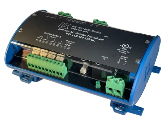
VT3-OL 120 VAC model shown. The VT3-OS is similar but supports 24 VAC/VDC power.
3-wire (wye) Line-Neutral
The 3-wire configuration only requires the three individual phases. This allows monitoring all three phases from line to line. The 3-wire model supports 120, 240 and 480 VAC nominal input.
The neutral terminal should not be used (no connect) and is disconnected internally. You can not use a 3-wire VT3 model in a 4-wire configuration.
Step 4: Power Supply
The VT3 requires an external power supply. Depending on the available power supply, two versions are available. The VT3-OS works with 24 VAC or 24 VDC, while the VT3-OL model is powered by 120 VAC. Using a 24 VAC/DC power supply allows the use of the smaller VT3-OS case, which may be preferred if space is a concern.
The power supply is isolated from the 3-phase inputs. Thus, the power supply neutral can be wired independently from the 3-phase neutral.
Product Operation
Depending on the model, three nominal input voltage ranges are supported (120/240/480 VAC) and the VT3 will measure the voltage on each individual line for each phase.
The VT3 provides an RMS output voltage for each line that is proportional to the input voltage as shown in the table below. It also provides another output that is the RMS average of all three phases.
If the voltage on any of the three line inputs falls below the minimum threshold, the Phase Loss Detection Relay will close, indicating a power loss or inadequate voltage on one of the phases.
For example, in a 120 VAC nominal 3-phase application the 0-150 VAC model would be used. The VT3 can individually monitor each of the three line inputs, one for each phase. Each output would then get connected to a data logger or PLC for monitoring the power health. The average output can also be monitored by the PLC or used with a compatible display to show the average RMS power.
If the voltage of any line falls under 90 VAC, the Phase Loss Detection Relay closes providing an alarm notification. The Phase Loss Detection Relay is a normally open SPST Form A relay that closes upon a low voltage event occurring.
For 240 and 480 VAC applications, the operation is similar as shown in the table below:

The VT3 provides true RMS output for each of the three phases. Voltage health can be monitored over time. Both over-voltage and under-voltage conditions can be logged for each phase independently.
A fourth output provides the average of all three RMS voltage outputs. This output can also be logged into the PLC or connected to a display providing overall average system voltage.
If any one of the three phases drops below the threshold, the Phase Loss Relay will close creating an alarm condition so that further action can be taken. For example, power can be completely shut down and operators notified that a critical power event has occurred.
Panel or DIN Mount Options
The VT3 Series is housed in a blue case that can be easily mounted. Simply snap it onto a DIN rail or mount it directly to a panel using the four screw holes.
DIN RAILS
DIN rails are long metal strips used to mount components onto equipment cabinet racks. They securely fasten components such as circuit breakers, power supplies, sensors & transducers, and control devices inside a panel cabinet or frame.
The VT3 case easily snaps onto common 35 mm Top Hat DIN rails (TS35 or EN50022). The 35 mm refers to the rail width from top to bottom.
The VT3 case has built-in clips that allow it to snap onto the rail. To remove the VT3 from the DIN rail, slide the clips away from the DIN rail to release the case from the rail.
If you need the actual DIN Rail, NK Technologies offers the DIN Rail Kit (Model: DINKIT) that includes a galvanized steel DIN Rail (175 mm/6.89 inches long) and two end stops to hold the unit place.


")
Panel Mount
The VT3 series case can also be panel mounted using the four mounting holes to screw or bolt the case directly to the inside panel.
Determine the Right Part Number
After determining the four configuration parameters, use the table below to choose the right part number.

Application Examples
1- Combining 3x VTU-DIN into a single VT3
2- Using the average output for a display
Application Examples: Using Single VT3 Instead of Three VTU
It is possible to monitor 3-phase voltage using three single-phase voltage transducers. Each phase can be measured independently.
The VT3 simplifies three-phase monitoring by measuring all three phases in a single device. This reduces the amount of wiring needed, saving both parts count (less wire and fewer terminal block splices) and reducing the overall labor required to install the solution.
A simple wiring diagram comparing three VTU single-phase transducers vs a single 3-phase transducer would look like the diagram below:

Less Wire. Less Headaches.
There are some obvious advantages to this solution.
1- Fewer Devices
2- Fewer Wires
3- Fewer Terminal Connections
4- Additional Features
a. Phase Loss Detection Relay
b. Average of the 3 RMS Phase Outputs
The VT3 Series is just easier to install. Install a single device (the VT3) instead of 3 individual devices (3xVTU’s).
Reducing wiring complexity saves labor, reduces part count (wires and terminals) and improves reliability and maintenance by making it easier to troubleshoot.
The VT3 solution eliminates nine wires (17 vs 26) which has cost benefits beyond using less copper. The chance for errors is reduced with nine fewer wires to cut, route, and connect.
There are 14 (35%) fewer connections to make (34 instead of 52), and the number of external terminals required are halved (20 to 9).


Application Examples: Using the VT3 with a Digital Display
The VT3 provides an average output that represents the average of the 3 individual RMS phase outputs. This allows you to hook up a separate display while running the primary outputs into the PLC.

